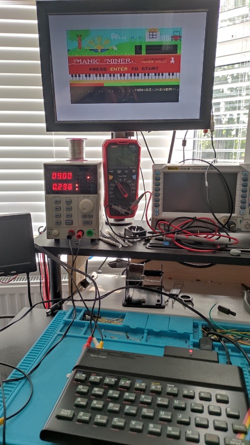
I like to have a display attached to my workbench to test the retro computers and consoles that I am working on – it’s cold in the garage where my old TV is. Most of the consoles I use have composite video output, or I have modified them to output composite video rather than their original RF output. To make my life simple the display needs to have the following legacy connections
- Analog RF – to test the original output before I mod them
- Composite – The standard input I use on most consoles
- HDMI – for use with a Chrome Cast to watch YouTube videos while I work
- SCART (Remember this!) – Some consoles output VGA over SCART.
I could use a modern display and connect a conversion box like the RetroTINK, but those are expensive, and I would still need a modern display (although I could probably pick up an old cheap monitor on eBay).
While investigating my options, I came across LCD controller boards on AliExpress that can be used to drive LCD panels, these seem to fit the bill in terms of inputs and are nice and cheap (~£12). Luckily I already had a couple of old laptops that I was about to bin.
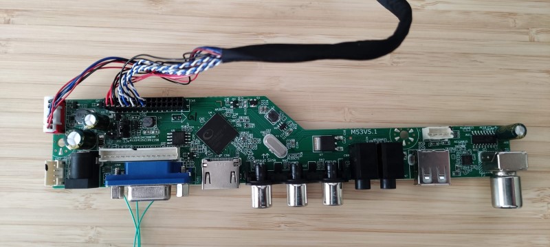
I bought two different boards to try with the panels, a T.SK105A.03, and an M53VS.01. The two boards look very similar and have the same capabilities. I don’t know what the difference is, but they do have different firmware. Neither have any documentation that I can find.
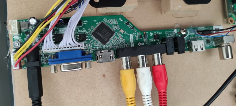
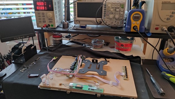
When selecting your board make sure that you get one that is compatible with your panel. There are several types with the largest difference being whether an external backlight driver board is needed, which is provided as a separate board. The next thing you need to do is find the correct cable to connect to your panel. With my panels, one needed the driver board and one didn’t – you can see from the photos above that the connections to the controller board are slightly different.
You can use the site Panelook.com to look up the specification of your panel. The important facts that you need to find are:
- Input voltage : lets you set the jumper on the controller board needed for the panel (3.3v, 5v or 12v)
- Signal Interface : Will tell you the cable you need to connect the board to the panel
- Resolution – needed to configure the firmware
Armed the a controller boards and cables I connected a panel and started testing.
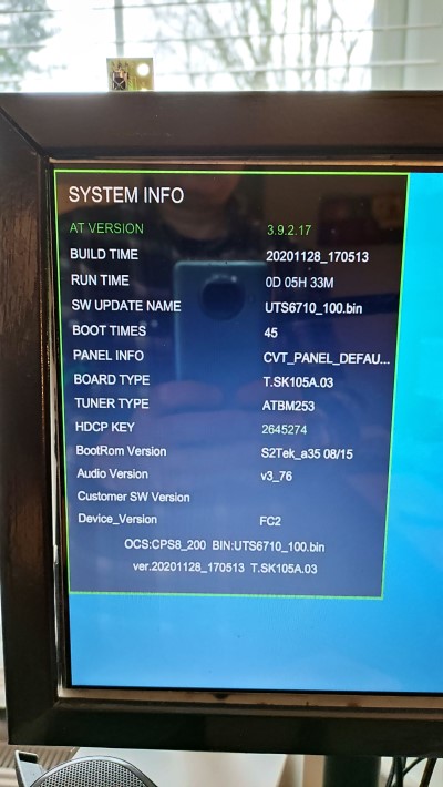
T.SK105A.03 Controller board
This was the board I started with and it started well…. but not for long. I ordered it with the specific firmware for my panel and it worked out of the box, but I quickly started to find devices that didn’t work with both its composite video and RF inputs. This rapidly became a real pain and I stopped using it, so, I decided to try updating the firmware to the latest version to see if this would make it more usable.
The firmware process is seemingly straightforward, load a file onto a USB stick and reboot the board with the stick installed. This proved to be unreliable, sometimes it would work and others not. I tried numerous sticks and various files and still don’t understand the magic combination of stick and file that makes it work? After lots of retries, I finally installed a working firmware but it was no better than the original.
The main ‘gotcha’ with the firmware for this board is that you need the specific firmware file to match the resolution of your panel.
I also found that pressing the ‘menu’ button and then typing the code ‘1147’ enters an admin menu system. This gives access to loads of options, but there is no documentation (that I could find), and many of the options are cryptic. There are probably options that I could change to make it more compatible… but I didn’t have a clue which ones.
M53VS.1 Controller board
I bought this as a generic board so thought that it would need a firmware update to match the resolution of the panel – so I flashed a new firmware. I later found out that the resolution can be changed using the remote – doh. Anyway, updating the firmware was easy and didn’t seem to suffer the same problems as the previous board.
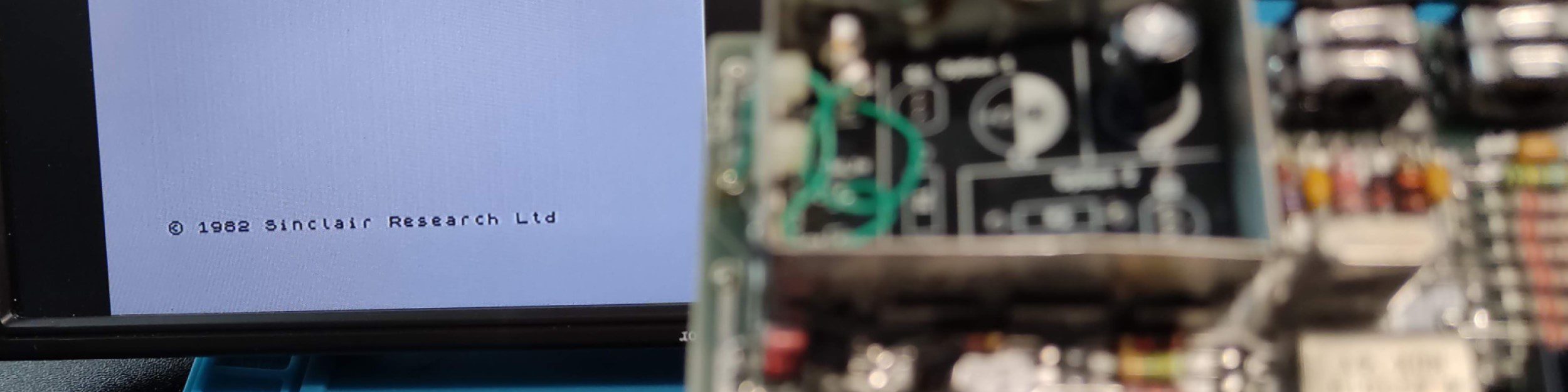
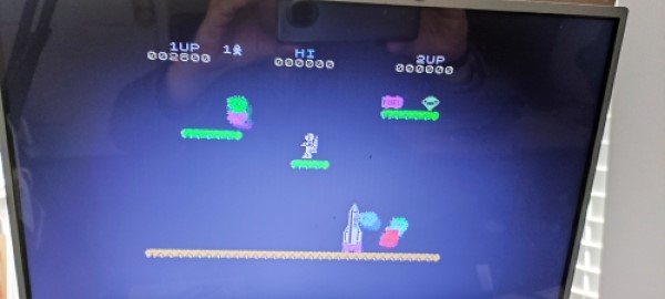
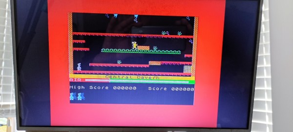
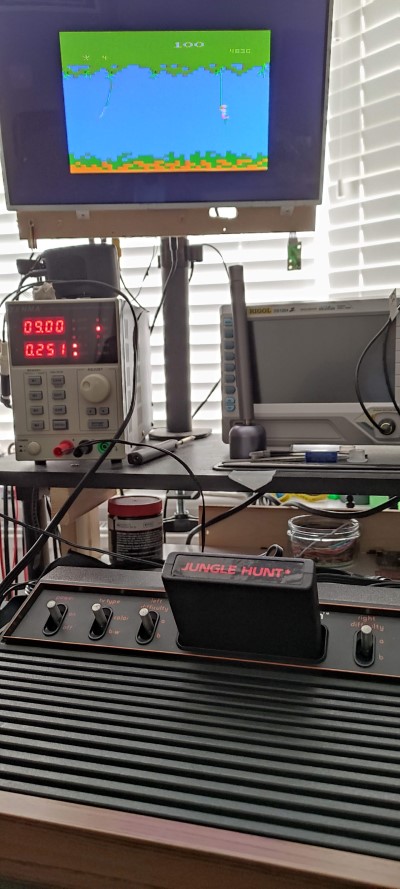
Testing the board, it quickly became apparent that this board is much more compatible with my devices – I haven’t tried RF yet, but all of the composite signals worked with no problems (ZX Spectrum, Commodore 64, Atari 2600).
The M53VS.1 also has an admin menu accessible by using the ‘input’ button and then typing ‘2580’ on the remote. The admin menu is also quite cryptic but not as bad and there aren’t as many random options.
Results
My testing is very subjective, but I found the M53VS.1 much easier to work with and more compatible with the various signals produced by my old consoles/computers. Your mileage may vary but hopefully, this will help you if you are trying to use one of these boards.