While fixing previous spectrums I bought a cheap motherboard in poor condition to use for spares. I knew it was rough from the seller’s pictures, and when it arrived in the post it was obvious that it had suffered from several previous attempts to ‘fix’ it – there were multiple visible broken tracks and many of the chips had obviously been replaced. Rather strangely there were also several bodge wires on the top side of the board running under chips – WHAT ??
Over Christmas 2020, with Covid lockdown, we weren’t going out much and I had run out of retro computers to fix; so I decided to see what I could do for this abused Spectrum.
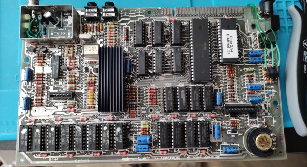
The first stage was to remove all of the main chips to see what state the motherboard was in. If it was beyond repair I could at least test the chips and reuse them later. I also removed the TV modulator – this was not going to be used again.
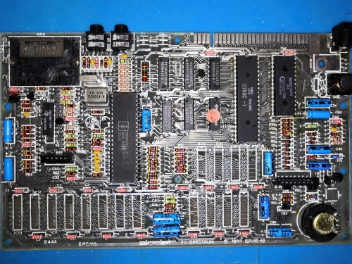
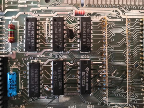
With all of the chips removed I checked the board over and replaced the previous bodge wires (on the back of the board this time). I also checked the continuity of all the data and address lines to check for other broken tracks – there were a couple around the lower memory, which I also fixed. Happy that I had done enough I added nice new sockets for all of the chips.
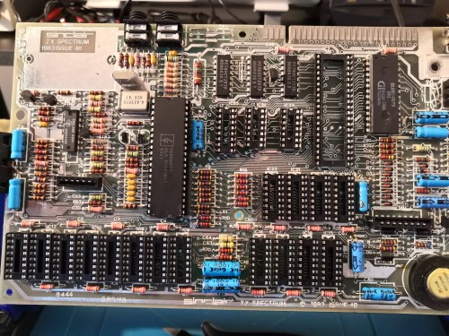
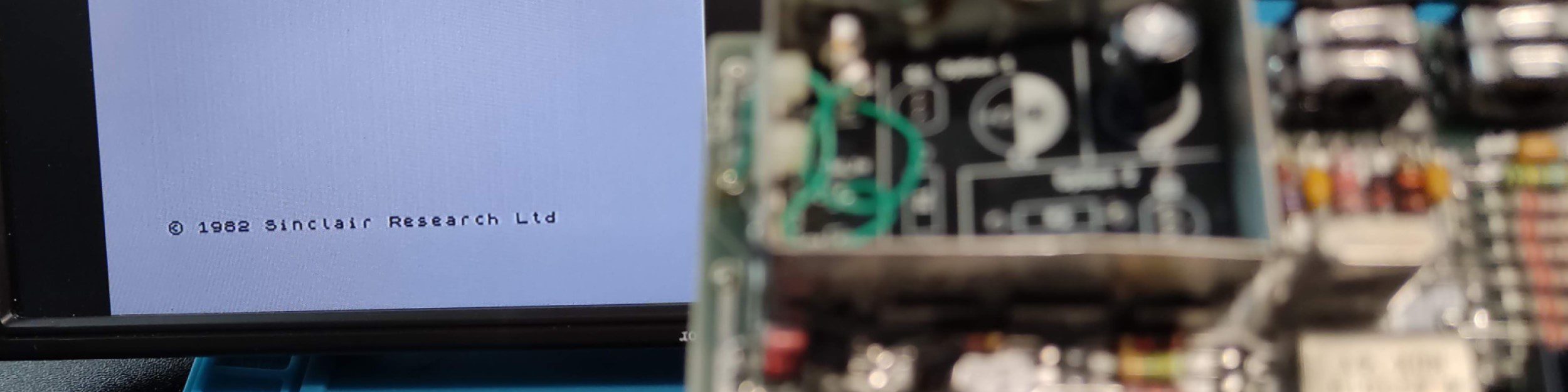
Installing chips back into the board I would love to say that it worked the first time – it didn’t. Following many more hours of debugging with my oscilloscope and tracing tracks against the schematics I finally began to see life as the diagnostics began to run and finally, a BASIC prompt was displayed.
Upgrade
With it finally working I decided it was going to be my ‘test bed’ Spectrum, everything was in sockets making it easy to test chips from other Spectrums. What I needed was built-in diagnostics. I decided to replace the standard EPROM with a custom multi-rom EEPROM. There are lots of guides online so I gathered a few components (mainly diodes, a switch, and a couple of bodge wires). I also replaced the TV modulator with a bespoke PCB composite mod.
The result was a custom ROM containing two images, selectable by a switch. I programmed two custom ROMs, one with diagnostics images and another with ‘enhanced’ BASIC and diagnostics – and it works great.
What do I do with it now? I wanted to have it displayed, accessible and functional. The idea of the ‘Naked Spectrum’ was born. The bare Spectrum motherboard is mounted on a display board, combined with a modern power supply and small monitor. I could then use it either as a rolling display or soak test for suspect chips.
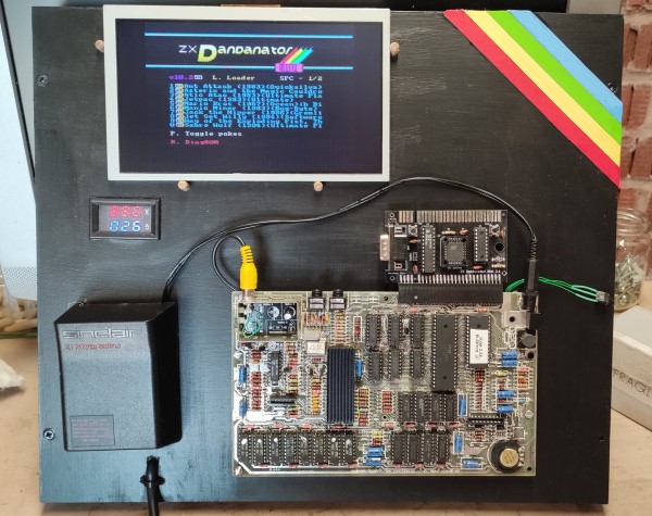
The visible power supply is just the outer case from an original supply, the system is powered by a modern switching power supply mounted on the back of the board. I have included volt and amp meters to monitor the current draw of the Spectrum (helping to identify problems/shorts quickly). The final piece is an 8″ TFT display running off the component signal. I added a Dandanator mini (see my previous post) to fast-load games and other diagnostics – the joystick port also allows me to drive the menus using a standard Atari joystick.
All done 🙂