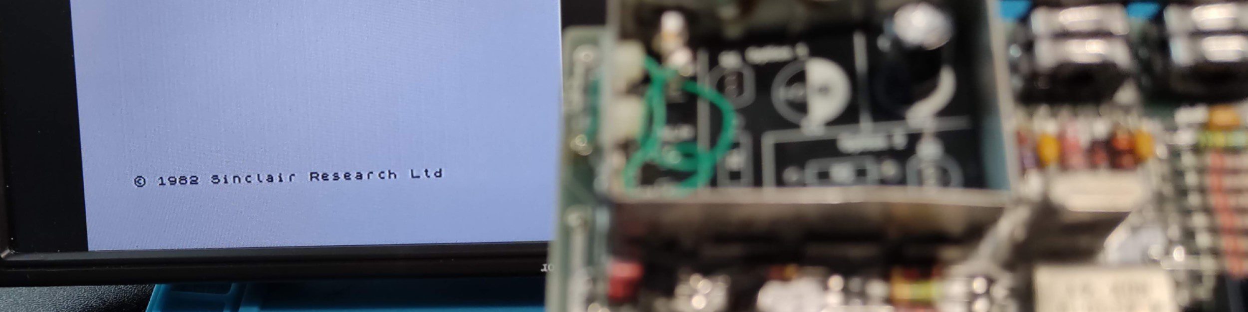
The Z80 processor is a classic microprocessor. Originally designed in the 1970’s variants are still in production, and are widely available today. My main interest is their use of the retro computers of the 1980s like the ZX81 and ZX Spectrum.
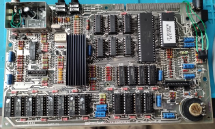
While fixing and refurbishing retro computers I regularly encounter dead Z80’s which can be difficult to diagnose. I have testers for various retro RAM chips, so I decided to build a standalone tester for Z80’s when I remove them. It would also allow me to check ‘new-old-parts’ that I buy from AliExpress.
After some research I decided to build a NOP generator as a starting point.
Design
So this is my simple design:
- Power up the Z80
- Generate a slow clock signal from another microcontroller
- The Z80 will place a request for memory location 0 on the address bus
- Respond with a NOP instruction (all zeros)
- The Z80 will do ‘nothing’ and request the next address
- Repeat
While the test is running the addresses being requested by the processor can be monitored to check that it is clocking up correctly. It’s a simple test but checks the basic fetch-execute cycle of the processor.
Prototype
The fist stage was to design a circuit…
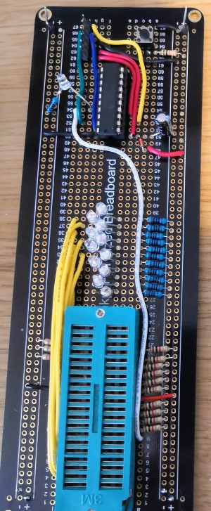
I decided to use a Microchip 16F690 as the clock driver chip for no other reason than I wanted to do some Microchip development and I have lots spare. The circuit is simple, the data lines are all pulled low using resisters and the address lines are pushed through LED’s for visual monitoring. The 16F690 generates a simple square wave clock to drive the Z80. I added a push button to activate the reset on the Z80 forcing it to restart the cycle. The final additional was an ICSP header to allow the 16F690 to be programmed in-circuit for development.
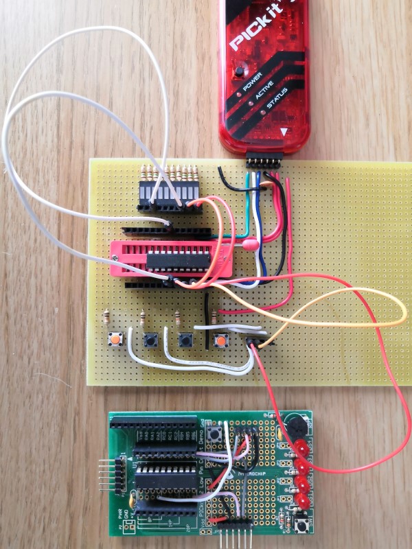
Development
While I was building the breadboard prototype I also took the opportunity to create a new test/programming board for PIC microcontrollers and my PICKit 3 programmer. I normally use the low pin count dev board, but it lacks peripherals and isn’t configurable.
Much to my surprise, the prototype worked and I watched the LEDs cycle through the addresses. There is a caveat that took some investigation to figure out. The Z80 also provides the DRAM refresh cycles which also use the address lines. This is done at set intervals during program execution ( I’m removing this on v2).
PCB Design
I had a working prototype so decided to learn how to create my own PCBs. I installed KiCad and headed to YouTube for some video tutorials. It didn’t take me long and I had a PCB designed and a nice 3D render.
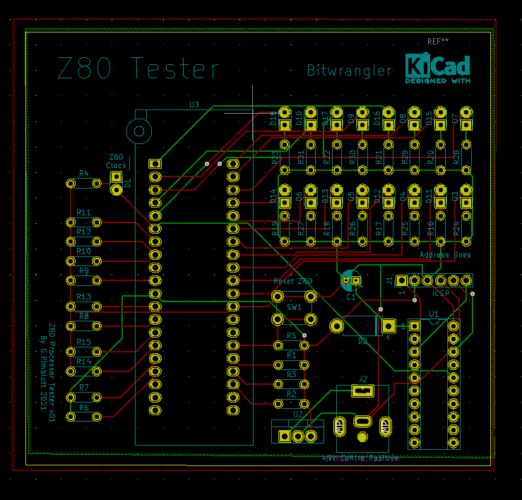
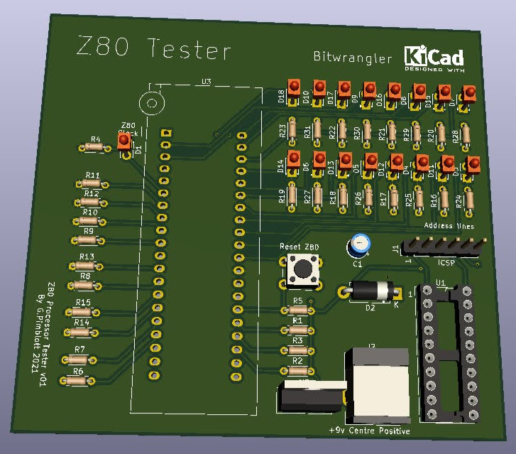
The next step was to upload to PCBWay for manufacture and the long wait for the boards to arrive from China.
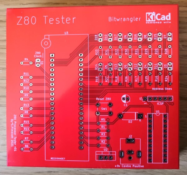
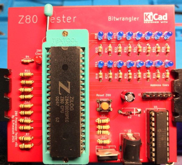
It took the normal three weeks for the PCBs to arrive, and populating the board took longer than I anticipated due to the number of LED’s and resisters. Next time I’ll use a resister pack and pre-made LED strip.
The result was great, the completed PCB worked just like the prototype – phew. I quickly ran through the stack of Z80s that I had previously removed as faulty from ZX Spectrums, followed by the ones received from AliExpress.
Success.
All of the code and PCB designs are on GitHub
I have started to prototype version 2 which will take the DRAM refresh into account and hopefully execute some real code on the Z80 not just NOP instructions, but that’s for another blog.
V1 Bill of materials
| Location | Component | Value |
| C1 | Capacitor | 100uf |
| D3->D18 | LEDs of your choice (I have used ultrabright blue) | |
| R16->R31 | Resister to match your LEDs I’ve used 150 Ohm | 150 Ohm |
| D1 | Red or Green LED | |
| R4 | Resister to match D1 | 150 Ohm |
| D2 | Diode | 1N4148 |
| R1,2,3,5,6,7,8,9,10,11,12,13,14,15 | Pulldown resisters | 10K |
| U1 | PIC Chip | PIC 16F690 |
| U2 | 5v Voltage regulator | 7805 |
| U3 | 40 Pin ZIF Socket | |
| J1 | 6 Header Pins | |
| J2 | 2.1 mm Barrel Jack – #9V Power Socket – watch the pin out I had to bodge mine in as it had the wrong pins placement |
To programme the PIC chip you can either use a PICKIT 2 or 3 or a TL866II Plus programmer