Looking through my previous blogs you might have seen me install Gotek drives into various retro computers to replace their floppy drives. Gotek drives floppy disk emulators originally designed to replace ageing drives in industrial equipment (or so I believe).
The FlashFloppy firmware replaces the original to make them more compatible with retro computers – allowing multiple disk images to be stored on a USB stick and selected via the screen.
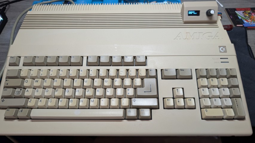
You can buy pre-flashed versions of the Gotek hardware from EBay , but it’s just as easy to buy a drive from Ali Express for £10-£15 and flash it yourself. Additionally, you can mod the hardware to include an OLED screen and rotary encoder to make disk selection even easier. The image below shows an Amiga that I have recently repaired and upgrading – sporting it’s FlashFloppy Gotek with custom 3D printed screen and encoder.
The instructions in the wiki are really good but there are a couple of gotchas that I have encountered and will document in this blog.
Getting ready to Flash
To flash your Gotek you will need the following
- PC to use for the flashing process
- Male USB A to Male USB A cable
- Jumper cable to set the drive into programming mode
Optionally, if you want to add an OLED screen and rotary encoder
- OLED screen
- Rotary encoder
- Soldering Iron – and associated skills
- Drill to mod the case for the rotary encoder or a 3D printer if you want a custom case – or a case that fits into your retro computer
- Male pin headers – 2.54″ pitch
I’m only going to cover the flashing here, but the wiki is excellent and can help with modding your drive once it is flashed.
Setting up the drive
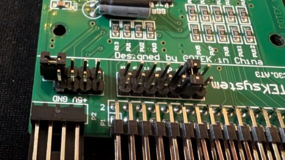
The first stage is to open the Gotek and remove the circuit board. You will see at the rear on the right there are two rows of vias (holes) that don’t have pin headers soldered into them. Two of these holes need to be bridged to put the board into programming mode. I find it easier to just solder header pins into all of the missing holes for future use; the other missing pins are used for the rotary encoder.


The first gotcha is the default jumpers setup in the main bank of header pins behind the floppy connector. All of the drives I have received have two jumpers in place – which in my experience stop the drive flashing – as shown in the picture below.
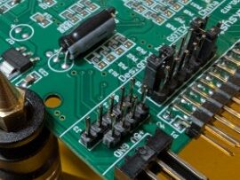
In my experience only the second two pins from the left (labelled S1 – looking from the front of the board) needs to be set the other jumper can be removed.
The programming pins also need to be jumped. The picture below shows the pins that I normally set.
See the documentation for more information
Flashing the drive
Once the setup is complete you can move on to programming the drive with FlashFloppy. All of the cheap Gotek boards I have bought from AliExpress have used Artery Micro-controllers – you can check this be reading the main square chip on the board.
To program the board you will need the Artery ISP driver and software which can be downloaded from the Artery website via the Resources -> Tools -> ISP download link (described as In-System-Programming tool supporting AT32 MCU). Unzip the files and install the DFU driver software to your PC.
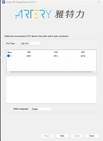
Plug the drive into your PC using the USB A to USB 1 cable and run the ArteryISPProgrammer.exe to start the flashing process. Your drive should be shown in the main list, select it and click next.
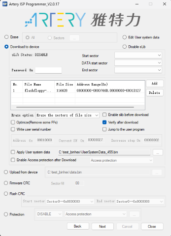
You will them be able to click through a couple of screens until you get to the main programming screen shown below. You will probably have been warned that the device is write-protected if this is a new device.
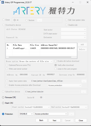
The first operation is to remove the write protection. Click the ‘Protection‘ button at the bottom on the screen and select ‘DISABLE’ and ‘Access protection‘ as shown above. Click ‘Next’
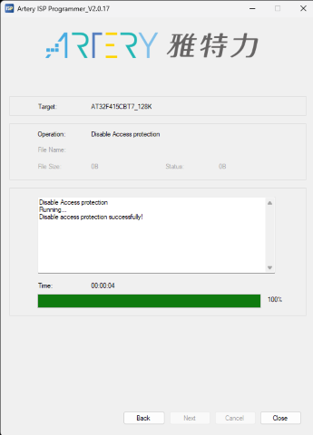
The screen will update to show the access protection being successfully disabled – hopefully…. I have had this fail but trying a second time it succeeds?
With this done, click ‘Back’ to return to the programming page.
Now download the latest firmware for your board from the FlashFloppy downloads page. Select ‘Download to device’ on the Artery software and add the firmware to the list. I also update the options to those shown below – to match the ones on the FlashFloppy documentation.
With the firmware set, click ‘Next’ and the flashing will start, and after a short wait your new FlashFloppy firmware will be installed.
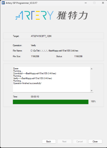
Now remove the programming jumper and your drive is ready to go 🙂 I’ll cover setting up the USB and installing mods in a later blog